
Version 5.2
Clusters |
|---|
| ||||||||
|
|
Version 5.2 |
||||||||||||||||||||||||||||||
|
|
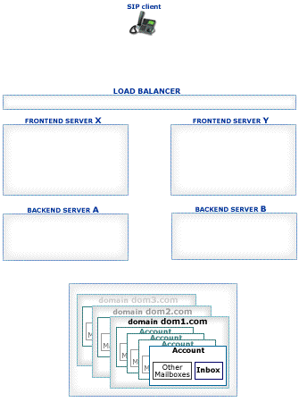
The CommuniGate Pro SIP Farm® feature allows several Cluster members to process SIP request packets randomly distributed to them by a Load Balancer.
Configure the Load Balancer to distribute incoming SIP UDP packets (port 5060 by default)
to the SIP ports of the selected SIP Farm Cluster members.
If your Cluster has Frontend Servers, then all or some of the Frontend Servers should be used as SIP Farm members.
To configure the SIP Farm Members, open the General page in the Settings WebAdmin realm and click the Cluster link:
The CommuniGate Pro Cluster maintains the information about all its Servers with the SIP Farm setting set to Member. Incoming UDP packets and TCP connections are distributed to those Servers using regular simple Load Balancers.
The receiving Server detects if the received packet must be processed on a certain Farm Server: it checks if the packet is a response or an ACK packet for an existing transaction or if the packet is directed to a Node created on a certain Server. In this case the packet is relayed to the proper Cluster member:
Packets not directed to a particular Cluster member are distributed to all currently available Farm Members based on the CommuniGate Pro SIP Farm algorithms.
To process a Signal, Cluster members may need to retrieve certain Account information (registration, preferences, etc.). If the Cluster member cannot open the Account (because the Member is a Frontend Server or because the Account is locked on a different Backend Server), it uses the inter-Cluster CLI/API to retrieve the required information from the proper Backend Server.
Several Load Balancer and network configurations can be used to implement a SIP Farm:
The frontend servers have IP addresses F1, F2, F3, ...
Configure the Load Balancer to process incoming UDP packets received on its VIP address and port 5060:SIP-specific techniques implemented in some Load Balancers allow them to send all "related" requests to the same server. Usually these techniques are based on the request Call-ID field and thus fail very often. CommuniGate Pro SIP Farm technology ensures proper request handling if a request or response packet is received by any SIP Farm member. Thus, these SIP-specific Load Balancer techniques are not required with CommuniGate Pro.
Many Load Balancers create "session binding" for incoming UDP requests, in the same way they process incoming TCP connections - even if they do not implement any SIP-special techniques.CommuniGate Pro SIP Farm distributes SIP request packets by relaying them between the frontend Servers,
according to the SIP Farm algorithms; the SIP Farm algorithms redirect the SIP response packets to the
frontend Server that has sent the related SIP request.
These CommuniGate Pro SIP Farm features make the Load Balancer "session binding" table useless (when used for SIP UDP)
It is very important to consult with your Load Balancer manufacturer to ensure that the Load Balancer does not use "session binding" for UDP port 5060 - to avoid the problem described above.
In this configuration frontend Servers have direct access to the Internet (they have IP addresses directly "visible" from the Internet).
Load Balancers with UDP "session binding" will have the same problems as described above.
DSR (Direct Server Response) is the preferred Load-Balancing method for larger installations.
To use the DSR method, create an "alias" for the loopback network interface on each Frontend Server. While the standard address for the loopback interface is 127.0.0.1, create an alias with the VIP address:Make sure that the kernel is configured to avoid ARP advertising for this lo interface (so the VIP address is not linked to any Frontend server in arp-tables). Subject to the Linux kernel version, the following commands should be added to the /etc/sysctl.conf file:
Note: Because MAC addresses are used to redirect incoming packets, the Load Balancer and all frontend Servers must be connected to the same network segment; there should be no router between the Load Balancer and frontend Servers.
Note: when a network "alias" is created, open the General Info page in the CommuniGate Pro WebAdmin Settings realm, and click the Refresh button to let the Server detect the newly added IP address.
The DSR method is transparent for all TCP-based services (including SIP over TCP/TLS), no additional CommuniGate Pro Server configuration is required: when a TCP connection is accepted on a local VIP address, outgoing packets for that connection will always have the same VIP address as the source address.
To use the DSR method for SIP UDP, the CommuniGate Pro frontend Server configuration should be updated:Load Balancer usually send some requests to servers in their "balanced pools". Lack of response tells the Load Balancer to remove the server from the pool, and to distribute incoming requests to remaining servers in that pool.
With SIP Farming switched on, the Load Balancer own requests can be relayed to other servers in the SIP Farm, and responses will come from those servers. This may cause the Load Balancer to decide that the server it has sent the request to is down, and exclude it from the service set.Each Media stream terminated in CommuniGate Pro (a stream relayed with a media proxy or a stream processed with a media server channel) is bound to a particular Cluster Member. The Load Balancer must ensure that all incoming Media packets are delivered to the proper Cluster Member.
The Server-wide WAN IP Address setting should be left empty on all Cluster Members.
The Cluster-wide WAN IP Address setting should specify the G0 address.
This method should not be used for large installations (unless there is little or no media termination): it allows you to allocate only 64000 ports for all Cluster media streams (each AVP stream takes 2 ports, so the total number of audio streams is limited to 32000, and if video is used (togther with audio), such a Cluster cannot support more than 16,000 concurrent A/V sessions.
The "multi-IP" method is useful for large installations. Each frontend has its own IP address, and when a Media Channel or a Media Proxy is created on that frontend Server, this unique IP address is used for direct communication between the Server and the client device or remote server.
The Network Settings of each Cluster Member can specify the same Media Port ranges, and the number of concurrent RTP streams is not limited by 64000 ports.
In the simplest case, all frontend Servers have "real" IP Addresses, i.e. they are directly connected to the Internet.
If the Load Balancer uses a DSR method (see above), then it should not care about the packets originating on the frontend Servers from non-VIP addresses: these packets either bypass the Load Balancer, or it should deliver them without any modification.
If the Load Balancer uses a "normal" method, it should be instructed to process "load balanced ports" only, while packets to and from "other ports" (such as the ports in the Media Ports range) should be redirected without any modification.
Configure the Load Balancer to host real IP Addresses G1, G2, G3,... - in addition to the VIP IP Address used to access CommuniGate Pro services.
Configure the Load Balancer to "map" its external IP address G1 to the frontend Server address L1, so all packets coming to the IP Address G1, port g (G1:g) are redirected to the frontend Server address L1, same port g (L1:g). The Load Balancer may change the packet target address to L1, or it may leave it as is (G1); When the Load Balancer receives a packet from the L1 address, port l (L1:l), and this port is not a port involved in a load balancing operations (an SMTP, POP, IMAP, SIP, etc.), the Load Balancer should redirect the packet outside, replacing its source address from L1 to G1: L1:l->G1:l.
Configure the Load Balancer in the same way to "map" its external IP addresses G2, G3, ... to the other frontend Server IP addresses L2, L3...
Configure the CommuniGate Pro frontend Servers, using the WebAdmin Settings realm. Open the Network pages, and specify the "mapped" IP addresses as Server-wide WAN IP Addresses: G1 for the frontend Server with L1 IP address, G2 for the frontend Server with L2 IP address, etc.
A "no-NAT" configuration with "normal" load balancing for POP, IMAP, and "DSR" load balancing for SIP (UDP/TCP), SMTP, HTTP User (8100).
The Load Balancer configuration:Startup configuration: ! server predictor round-robin ! server real fe5 64.173.55.180 port pop3 port pop3 keepalive port imap4 port imap4 keepalive port 5060 port 5060 keepalive port smtp port smtp keepalive port 8100 port 8100 keepalive ! server real fe6 64.173.55.181 port pop3 port pop3 keepalive port imap4 port imap4 keepalive port 5060 port 5060 keepalive port smtp port smtp keepalive port 8100 port 8100 keepalive ! server real fe7 64.173.55.182 port pop3 port pop3 keepalive port imap4 port imap4 keepalive port 5060 port 5060 keepalive port smtp port smtp keepalive port 8100 port 8100 keepalive ! server real fe8 64.173.55.183 port pop3 port pop3 keepalive port imap4 port imap4 keepalive port 5060 port 5060 keepalive port smtp port smtp keepalive port 8100 port 8100 keepalive ! ! server virtual vip1 64.173.55.164 predictor round-robin port pop3 port imap4 port 5060 port 5060 dsr port smtp port smtp dsr port 8100 port 8100 dsr bind pop3 fe5 pop3 fe6 pop3 fe7 pop3 fe8 pop3 bind imap4 fe5 imap4 fe6 imap4 fe7 imap4 fe8 imap4 bind 5060 fe8 5060 fe7 5060 fe6 5060 fe5 5060 bind smtp fe8 smtp fe7 smtp fe6 smtp fe5 smtp bind 8100 fe5 8100 fe6 8100 fe7 8100 fe8 8100 ! ip address 64.173.55.176 255.255.255.224 ip default-gateway 64.173.55.161 ip dns server-address 64.173.55.167 ip mu act endNote: you should NOT use the port 5060 sip-switch, port sip sip-proxy-server, or other "smart" (application-level) Load Balancer features.
script start "Alteon AD3" 4  /**** DO NOT EDIT THIS LINE!
/* Configuration dump taken 21:06:57 Mon Apr  9, 2007
/* Version 10.0.33.4,  Base MAC address 00:60:cf:41:f5:20
/c/sys
        tnet ena
        smtp "mail.communigate.com"
        mnet 64.173.55.160
        mmask 255.255.255.224
/c/sys/user
        admpw "ffe90d3859680828b6a4e6f39ad8abdace262413d5fe6d181d2d199b1aac22a6"
/c/ip/if 1
        ena
        addr 64.173.55.176
        mask 255.255.255.224
        broad 64.173.55.191
/c/ip/gw 1
        ena
        addr 64.173.55.161
/c/ip/dns
        prima 64.173.55.167
/c/sys/ntp
        on
        dlight ena
        server 64.173.55.167
/c/slb
        on
/c/slb/real 5
        ena
        rip 64.173.55.180
        addport 110
        addport 143
        addport 5060
        addport 25
        addport 8100
        submac ena
/c/slb/real 6
        ena
        rip 64.173.55.181
        addport 110
        addport 143
        addport 5060
        addport 25
        addport 8100
        submac ena
/c/slb/real 7
        ena
        rip 64.173.55.182
        addport 110
        addport 143
        addport 5060
        addport 25
        addport 8100
        submac ena
/c/slb/real 8
        ena
        rip 64.173.55.183
        addport 110
        addport 143
        addport 5060
        addport 25
        addport 8100
        submac ena
/c/slb/group 1
        add 5
        add 6
        add 7
        add 8
        name "all-services"
/c/slb/port 1
        client ena
/c/slb/port 5
        server ena
/c/slb/port 6
        server ena
/c/slb/port 7
        server ena
/c/slb/port 8
        server ena
/c/slb/virt 1
        ena
        vip 64.173.55.164
/c/slb/virt 1/service pop3
        group 1
/c/slb/virt 1/service imap4
        group 1
/c/slb/virt 1/service 5060
        group 1
        udp enabled
        udp stateless
        nonat ena
/c/slb/virt 1/service smtp
        group 1
        nonat ena
/c/slb/virt 1/service 8100
        group 1
        nonat ena
/
script end  /**** DO NOT EDIT THIS LINE!
vlan external {
   tag 4093
   interfaces
      1.1
      1.2
}
stp instance 0 {
   vlans external
   interfaces
      1.1
         external path cost 20K
         internal path cost 20K
      1.2
         external path cost 20K
         internal path cost 20K
}
self allow {
   default
      udp snmp
      proto ospf
      tcp https
      udp domain
      tcp domain
      tcp ssh
}
self 64.173.55.176 {
   netmask 255.255.255.224
   vlan external
   allow all
}
partition Common {
   description "Repository for system objects and shared objects."
}
route default inet {
   gateway 64.173.55.161
}
monitor MySMTP {
   defaults from smtp
   dest *:smtp
   debug "no"
}
profile fastL4 CGS_fastL4 {
   defaults from fastL4
   idle timeout 60
   tcp handshake timeout 15
   tcp close timeout 60
   loose initiation disable
   loose close enable
   software syncookie disable
}
pool Frontends {
   monitor all MySMTP and gateway_icmp
   members
      64.173.55.180:any
      64.173.55.181:any
      64.173.55.182:any
      64.173.55.183:any
}
node * monitor MySMTP
virtual address 64.173.55.164 {
   floating disable
   unit 0
}
virtual External {
   translate address disable
   pool Frontends
   destination 64.173.55.164:any
   profiles CGS_fastL4
}